Hey everyone I've been pulling my hair out trying to piece this together, I emailed moog and this is what they told me.
Since our Moogerfoogers are designed to work with both passive and active CV devices, wiring them up to a patchbay can be tricky. Basically, the internal wiring of the CV jacks is like this:
Tip - Receives incoming voltage to control parameter
Ring - +5v. When nothing is plugged into the jack, this is shorted to the Tip. This way the Tip is constantly supplied with +5v.
Sleeve - Ground
The problem here is that, in order to have the pedals hooked up to the patch bay, you will need to have cables permanently plugged in to the CV jacks. This breaks the connection between the Ring and Tip and drops the Tip voltage down to 0.
To overcome this, you will need to wire your patch bay jacks so that the Tip and Ring are shorted together whenever there is no cable plugged in. When you insert a patch cable, it should break the connection and replace the Tip voltage with whatever voltage is coming in.
I'm afraid this this as best as I can explain it. Good luck and let me know if you need anything else.
This sound different then the info Ive been reading on here seank, latigid on I have the same patchbay as seank do u think you can help me a little with info on the soldering side of things just maybe explain a little more where I should be soldering the patchbay pcb, http://i43.tinypic.com/2w2hufq.jpg Do i solder to this side or the other side? this is the last thing I need done. help please.
racking the fooger collection
-
backtothelab
- Posts: 24
- Joined: Fri Jun 17, 2011 8:00 pm
Re: racking the fooger collection
heres a pic

-
latigid on

- Posts: 1579
- Joined: Mon Jan 30, 2006 3:47 pm
- Location: Auckland, New Zealand
Re: racking the fooger collection
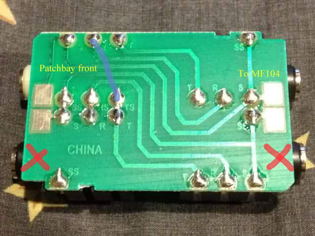
From the white socket bridge the R and TS connections. The white socket receives the TRS cable from the MF-104.
Presumably the TS means "tip switch"
In this configuration the bottom row won't work as it is intended. If you still need to use these patch points you could cut traces on the PCB from the white socket to the bottom right socket and bridge the connections back together with hookup wire.
You only have one switched socket per PCB so your options are limited.
YMMV.
-
backtothelab
- Posts: 24
- Joined: Fri Jun 17, 2011 8:00 pm
Re: racking the fooger collection
I can return this patch bay if its not going to work properly. Latigid on can u recommend a patchbay that will work? Thanks
-
latigid on
- Posts: 1579
- Joined: Mon Jan 30, 2006 3:47 pm
- Location: Auckland, New Zealand
Re: racking the fooger collection
As per PM:
hth,
hth,
-
backtothelab
- Posts: 24
- Joined: Fri Jun 17, 2011 8:00 pm
Re: racking the fooger collection
Thanks for the pic that makes it easy  Im assuming I dont use the X jacks, and I just bridge together the r to the ts no 100k resistor. SeanK is this what you ended up doing? or did you figure out a way to use both jacks?
Re: racking the fooger collection
i seriously have no idea. that installation was a whirlwind of making custom trs/power cables, case, patchbay template, and rack modifications. the easiest way to check is to just have it connected to your delay pedal with some sound going through it and touch a resistor to the contacts. that's how i figured it out.
-
krismiller1982
- Posts: 33
- Joined: Sat Aug 18, 2012 4:19 am
Re: racking the fooger collection
DITTO @Seank
Re: racking the fooger collection
Has anyone tried to use the fooger rack with the SKB 19" DJ command center?
http://www.skbcases.com/music/products/ ... 02&o=&s=78
It looks like the middle space is only 5 units while the fooger rack is 6 units...
http://www.skbcases.com/music/products/ ... 02&o=&s=78
It looks like the middle space is only 5 units while the fooger rack is 6 units...
sesshinnofi.bandcamp.com
soundcloud.com/no-fi-sound-system
soundcloud.com/no-fi-sound-system
Re: racking the fooger collection
Yeah, you could fit one Fooger sideways with that one...
Stephen
.
Stephen
.
Re: racking the fooger collection
If you could put 3 foogers in the middle and then 2 cps above that would be pretty sick. The mooger rack plate is huge though wow, I racked up a fooger, cp-251 and an expresison pedal on it. The expression pedal fits perfectly sideways, the screws even line up, and then the CP can be racked above it.Vsyevolod wrote:Yeah, you could fit one Fooger sideways with that one...
Stephen
.
sesshinnofi.bandcamp.com
soundcloud.com/no-fi-sound-system
soundcloud.com/no-fi-sound-system
-
pelissarim
- Posts: 22
- Joined: Sat Mar 21, 2015 5:06 pm
Re: racking the fooger collection
So does the +5V always on with nothing is plugged in apply to the rear Voyager ports as well? Because I am going to build a front passthru port for the rear TRS ports on my Voyager. I am just trying to make sure I do everything right. I asked a few questions directly to Moog but have not had a response yet.
Re: racking the fooger collection
So for those of you in a studio setting, I found a easy, if not exactly cheap solution. This alleged laptop stand is 18" across almost exactly, and fits three foogers pretty much perfect. 70 bucks but it does a good job.
Does the job well enough, and lets me set them above the MS-20

As a bonus the bottom of it gives backing for the CP-251 and SQ-1 so they don't fall back. Good times.
Does the job well enough, and lets me set them above the MS-20
As a bonus the bottom of it gives backing for the CP-251 and SQ-1 so they don't fall back. Good times.